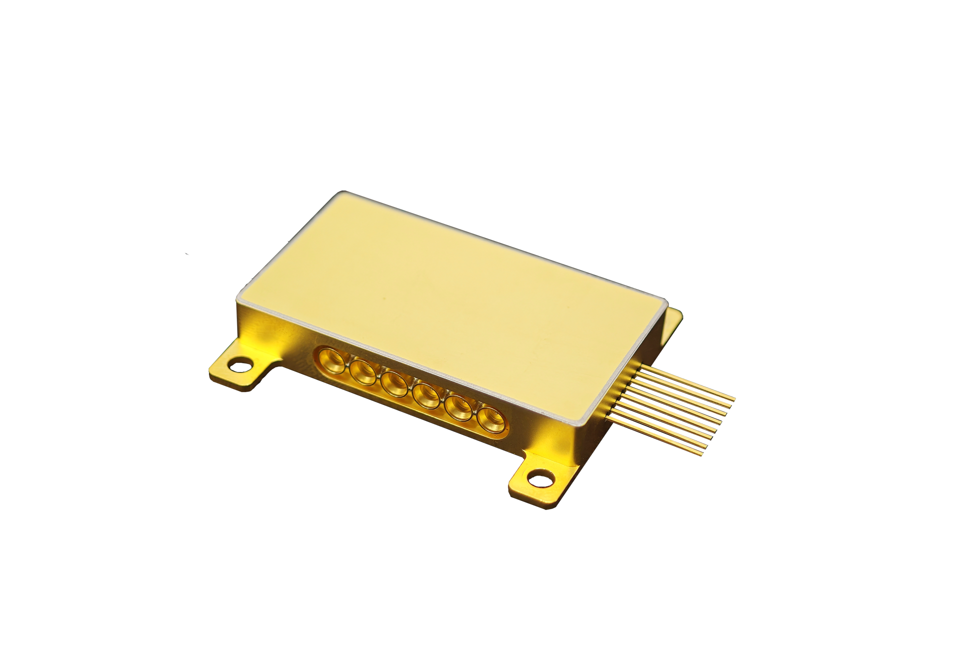
Electro-optic performance describes how effectively an electrical signal controls light without excessive loss, voltage, distortion, or instability. They evaluate that performance through a group of linked parameters rather than a single outlier value.
Higher bandwidth is useful when the driver can reach it, optical power remains adequate, and the delivered waveform preserves the required quality. By placing lithium niobate in a thin film, designers gain tightly confined optical waveguides and electrodes positioned for strong field overlap.
Traveling-wave structures can extend interaction over distance while maintaining high-frequency response. These design choices can reduce voltage and increase bandwidth compared with larger bulk geometries, although fabrication tolerance and package transitions become increasingly important.
Published TFLN Devices include intensity products up to 110 GHz, 40 GHz phase and IQ products, and a 25 GHz frequency-comb device. Their published voltage and loss limits illustrate several optimization points. They use them to build realistic subsystem models and then replace assumptions with measured response from packaged samples.
Thin-Film Geometry Strengthens the Interaction Between RF and Light
A TFLN modulator guides light in a thin lithium-niobate layer while an adjacent electrode carries the RF waveform. Efficient overlap allows a useful phase change with less electrical swing. At high frequency, the electrode must also maintain impedance and travel at a velocity compatible with the optical wave.
Mismatch reduces interaction and produces response roll-off or ripple. The TFLN device portfolio uses interferometers for intensity control, direct phase paths for phase modulation, or nested structures for IQ signals. The material platform is shared, but each circuit distributes loss, voltage, and control differently.
They select the topology according to the operation needed, avoiding comparisons that treat a simple phase path and a complex coherent circuit as equivalent products. Compact geometry can improve integration, yet it can increase sensitivity to lithography, sidewall quality, and coupling.
They request statistical device data and inspect how the package aligns fibers and launches RF energy. A well-characterized die can lose its advantage through a poor transition, while a controlled package can preserve useful performance even if the chip is not an isolated outlier.
Performance Improvement Is a Balance of Bandwidth, Voltage, and Loss
At the upper end, the 67/110 GHz intensity device combines insertion loss below 4.5 dB with half-wave voltage below 3 V. This TFLN modulator can reduce driver demand while supporting fast waveforms, provided the package and cable path preserve response.
They examine the complete transfer function and required extinction at operating temperature before setting the amplifier specification. A 40 GHz phase product lists loss below 3.5 dB and half-wave voltage below 3.5 V, while the IQ device is below 6.5 dB and 3.5 V. The figures for these TFLN devices show why complexity affects loss.
They compare each device against the function delivered and account for external splitters or combiners that an apparently lower-loss alternative might require. Frequency-comb generation uses another balance: 25 GHz RF bandwidth, half-wave voltage below 2.5 V, and insertion loss below 9 dB.
Strong modulation can create many spectral lines but consumes RF and optical margin. They optimize line quality, power per line, and stability, demonstrating that electro-optic improvement must be defined by the application rather than by one component metric.
Verification Must Capture Packaging and Operating Variation
Package verification begins with calibrated electrical reference planes. They measure connector, cable, and launch loss, then separate them from the intrinsic response where possible. For a TFLN modulator, impedance discontinuities can create standing waves that vary with frequency and temperature.
Time-domain and frequency-domain data together help locate the limiting transition and guide corrective design. Environmental qualification should exercise TFLN devices across optical wavelength, polarization, input power, bias condition, and environmental range. They record drift, hysteresis, restart behavior, and control-voltage demand.
Multiple units reveal the distribution that driver and firmware teams must support, preventing a control scheme from being tuned around one unusually selected sample. Production readiness depends on correlation among wafer tests, packaged-device tests, and final subsystem results.
They define guard bands and monitor trends rather than relying solely on pass or fail. When a process shift occurs, correlated data can show whether it affects electrical efficiency, optical loss, coupling, or package response, accelerating investigation and protecting shipments. Measurement uncertainty can obscure small performance gains.
They document calibration, fixture removal, repeatability, and environmental conditions before comparing samples. When two devices differ by less than the combined uncertainty, they avoid declaring a winner and instead test the subsystem outcome that the difference is expected to influence.
The thin-film platform improves electro-optic design by offering a strong and fast interaction in a compact geometry. The practical gain is the combined operating window across bandwidth, drive voltage, loss, waveform quality, and stability. They quantify that window in the configuration customers will use, both at a convenient chip-level reference plane.
A disciplined comparison includes the driver, laser, package, fibers, receiver, controls, manufacturing yield, and test time. This broader model may reveal that a modest improvement in voltage or loss has substantial system value, or that a headline bandwidth adds little because another interface is already limiting.
Evidence keeps optimization focused on commercial outcomes. Bandwidth, voltage, loss, stability, and waveform quality form a combined operating window. Measurements of Liobate modulators with representative drivers and packages can show whether that window remains consistent across the production distribution.
