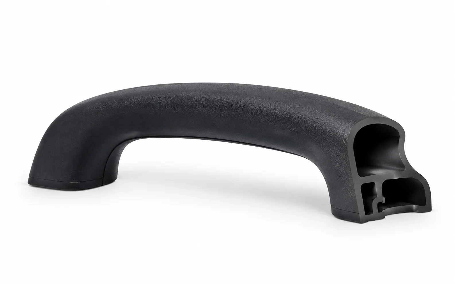
A molded part does not become difficult simply because its shape looks complicated. The real tooling problem appears when a feature cannot leave the mold along the normal opening direction. Side holes, undercuts, recessed details, and certain threaded or interlocking geometries can create a physical conflict between the finished part and a conventional mold. In those situations, injection molding slides become a way to change the direction in which the tooling releases the feature.
That makes slider selection less about adding a sophisticated mechanism and more about solving a geometric constraint. The most effective design process starts with the part, identifies where extraction becomes impossible, and then determines what movement the mold needs to release that region.
The Real Trigger Is Geometry, Not Part Complexity
A part with dozens of surfaces may still work with a conventional mold if all of those surfaces have suitable draft relative to the mold-opening direction. Conversely, one small lateral hole can force a significant change in tooling architecture.
The critical question is therefore simple: which feature prevents the molded component from separating cleanly from the mold?
An undercut is significant because the steel surrounding that feature can physically lock the plastic part in place. A slider creates an additional moving section of the mold that can form such geometry and then withdraw before ejection. HordRT describes sliders as movable mold components used for undercuts, side holes, overhangs, threads, and other features that cannot be produced through a standard opening movement.
Product geometry should consequently be reviewed before the tooling concept is fixed. A mechanism selected without understanding the exact obstruction can solve one feature while creating unnecessary complexity elsewhere.
Start With the Direction the Part Must Leave the Mold
Treating ejection as a directional problem gives mold design a clearer logic: the key question is not whether a feature looks complex, but which direction the part must move to clear the surrounding steel. Consider a component with a side opening. The opening may be straightforward to machine into the finished tool, but machining the cavity does not solve the release problem. If steel occupies the side of the opening, the molded plastic cannot simply move vertically away from it.
The required movement now has at least two stages: the tooling must first clear the lateral feature, and the main mold-opening movement can then release the part. A slider provides that additional motion.
HordRT’s reference explains that conventional sliders move laterally, generally perpendicular to the primary mold opening and closing direction. The mechanism can therefore create a feature from one direction while allowing the finished part to leave from another.
This way of viewing the problem is useful during design review. Rather than asking whether a component “needs a slider,” engineers can map every potential interference against the intended ejection direction.
Side Features Turn Ejection Into a Mechanical Problem
Side geometry is often where an apparently simple plastic component becomes a tooling exercise.
A lateral opening may require a core pin extending from the slider into the mold cavity. An undercut may require the same moving section to carry a shaped insert. Threads or rotational features can introduce still different movement requirements. HordRT identifies straight, angled, and rotary slider arrangements as distinct approaches for different feature geometries.
Feature depth matters as well. A shallow side detail and a deep internal undercut do not necessarily place the same demands on the mechanism. The available space around the product can also restrict how far the slider can travel.
Consequently, slider design should begin with the geometry that has to be formed, not with a preferred mechanism. The feature determines the required direction and travel; the available mold space then determines whether that movement can be packaged effectively.
Movement Must Be Designed Around the Feature
A slider is not merely a block that moves sideways. Its movement has to be synchronized with the molding cycle.
HordRT’s reference describes a mechanism involving components such as a core pin, slider base, angled or cam pin, guide rails, and return springs. During mold closing, the mechanism positions the slider for molding; during opening, the slider retracts so the molded component can be released.
That sequence creates several engineering questions.
How far must the slider retract before the part is clear? Does the available stroke provide sufficient clearance? Can the mechanism maintain the required position during injection? Are the guiding surfaces adequately supported? What happens if friction or wear changes the movement over repeated cycles?
Tolerance therefore belongs to the mechanism as well as the molded feature. HordRT specifically identifies precise fit and tolerance control as important for avoiding misalignment or jamming.
A Slider Is Also a Maintenance Decision
Adding motion to a mold introduces components that move against one another. That changes the maintenance profile of the tool.
Guide surfaces, pins, rails, and other moving interfaces are exposed to friction and repeated cycling. HordRT notes lubrication as a consideration for reducing friction and wear, while also identifying wear and maintenance as challenges associated with sliders.
The implication for tooling design is broader than simply choosing durable components. Access for inspection, lubrication, adjustment, and replacement should be considered while the mechanism is still being designed.
Cooling deserves attention too. The reference identifies cooling as one of the design considerations for slider mechanisms. A slider occupies physical space inside the tool, so cooling arrangements may need to coexist with moving components and the feature being formed.
Know When a Different Tooling Strategy Makes More Sense
Not every difficult-looking feature automatically requires a slider.
A design change may sometimes remove the undercut altogether. A feature can potentially be redesigned around the primary mold-opening direction, depending on the product’s functional requirements. In other cases, a different moving mechanism or secondary operation may provide a more suitable manufacturing route.
The decision should therefore compare the geometry that must be produced with the mechanical complexity introduced by the tooling solution.
Slider mechanisms can reduce the need for secondary operations when they directly form otherwise inaccessible features, but they also add moving components, setup requirements, and maintenance demands. The correct choice depends on which constraint dominates the particular part.
Review the Mechanism Before Steel Is Cut
Questioning a slider is generally more productive before mold construction begins, when a design review can still trace the path from product feature to mold movement: identify the obstructing geometry, establish the primary opening direction, define the required lateral or rotational movement, check available stroke and clearance, and then examine maintenance access.
This approach also creates a clearer conversation between product designers and tooling engineers. Instead of discussing a slider as a generic mold component, both sides can evaluate a specific feature and the physical movement required to manufacture it.
For manufacturers such as HordRT, where injection molding is integrated with tooling development, this geometry-to-mechanism review can be incorporated into the broader tooling process. Their published capabilities include prototype, bridge, production, and export tooling alongside injection molding services.
The value of injection molding slides is not their complexity. Their value lies in resolving a specific geometric conflict between the molded part and the direction of mold release.
Once that conflict is identified early, the slider becomes a deliberate engineering solution rather than an after-the-fact response to an impossible ejection condition. HordRT’s tooling guidance similarly positions slider design around geometry, movement, fit, lubrication, cooling, and long-term operation rather than treating the mechanism as an isolated component.
